
Exploring the engineering behind catalyst substrates—the structural backbone of every emissions aftertreatment system—and their role in providing high geometric surface area, optimal flow distribution, and thermal/mechanical durability for automotive, industrial, and stationary catalyst applications.
Every catalytic converter—whether a Three-Way Catalyst (TWC), Diesel Oxidation Catalyst (DOC), Selective Catalytic Reduction (SCR) catalyst, or catalytic oxidizer—requires a physical structure to support the active washcoat and precious metals. The **catalyst substrate** provides this foundation. Exhaust gases flow through or across the substrate, diffusing into the porous washcoat where chemical reactions occur. The substrate’s geometry, material composition, and cell density directly determine pressure drop, mass transfer efficiency, light-off behavior, and durability. This fundamental structural support enables the catalyst to achieve high conversion efficiency (95–99%+) while withstanding extreme thermal cycling, vibration, and chemical attack over hundreds of thousands of kilometers or years of continuous industrial operation.
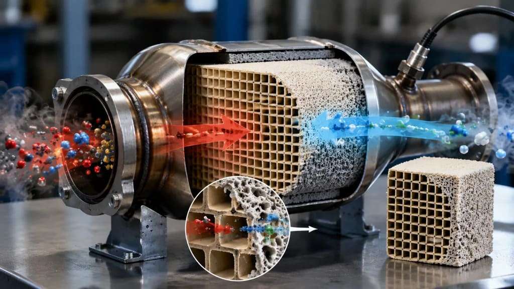
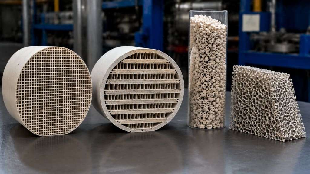
Catalyst substrates are not passive components—they are engineered to actively shape the exhaust flow, heat transfer, and reaction kinetics. The two dominant substrate architectures are:
| Substrate Type | Architecture | Primary Applications | Key Characteristics |
| Honeycomb Monolith (Flow-Through) | Parallel, straight channels | TWC, DOC, SCR, CO, RCO | Low pressure drop, high geometric surface area, rapid light-off |
| Wall-Flow Filter | Alternating plugged channels | DPF, GPF | High filtration efficiency, high soot storage capacity |
| Packed Bed (Pellets) | Randomly packed spheres or extrudates | Older converters, industrial VOC, some SCR | High thermal mass, tolerant to poisons, higher pressure drop |
| Foam / Mesh | Open-cell reticulated structure | Specialty applications (marine, stationary gas engines) | High turbulence, good mass transfer, lower surface area |
This page focuses on the most common architecture: the ceramic honeycomb monolith (flow-through). Wall-flow filters (DPF, GPF) are covered in their respective technical routes.

The journey from raw materials to a finished, washcoated catalyst substrate follows a precise manufacturing and engineering path.
The substrate material determines thermal durability, mechanical strength, and cost.
Cordierite (2MgO•2Al₂O₃•5SiO₂) – The Industry Standard
Silicon Carbide (SiC) – High Performance, High Temperature
Aluminum Titanate (AT) – Emerging Alternative
Metallic Substrates – Thin-Wall, Fast Light-Off
Material Selection Guide:
Requirement | Recommended Material |
Lowest cost, gasoline TWC | Cordierite |
Highest temperature, heavy-duty DPF | SiC (segmented) |
Fastest light-off, motorcycle | Metal (FeCrAlloy) |
Balance of cost & durability, passenger DPF | Cordierite or AT |
High cell density (>900 cpsi), low backpressure | Ultra-thin-wall cordierite or metal |
The substrate manufacturing process begins with a batch of raw ceramic powders, binders, plasticizers, and water.
Process flow: 1. Mixing: Powders (talc, kaolin, alumina, silica for cordierite; SiC grains + binder for SiC) are dry-mixed, then water and organic binders (methylcellulose, polyethylene glycol) are added to form a plastic paste. 2. Extrusion: The paste is forced through a die with a grid of slots. The die design determines: – Cell density (cpsi – cells per square inch): 100 to 1,200+ cpsi. Higher density = more surface area but higher pressure drop. – Wall thickness (mil – thousandths of an inch): 2–12 mil (0.05–0.30 mm). Thinner walls reduce pressure drop and thermal mass (faster light-off) but reduce mechanical strength. – Channel shape: Square (most common), triangle, hexagon, or sinusoidal. 3. Drying: The “green” (unfired) monolith is dried with microwave or hot air to remove water. 4. Cutting: Extruded logs are cut to customer-specified lengths and shapes (round, oval, racetrack, or asymmetric). 5. Firing (sintering): Parts are fired in kilns at 1,300–1,450°C (2,372–2,642°F). During firing: – Organics burn off (leaving porosity). – Ceramic particles sinter (bond together). – For cordierite: The reaction forms the crystalline cordierite phase. 6. Canning (for wall-flow): For SiC DPF substrates, individual segments (typically 30–50 mm squares) are bonded with a ceramic cement into a larger cylindrical or oval block—the segmentation allows thermal expansion without cracking.
Key geometric parameters:
Parameter | Range | Impact |
Cell density | 100–1,200 cpsi | Higher = more surface area, higher ΔP |
Wall thickness | 2–12 mil (0.05–0.30 mm) | Thinner = faster light-off, lower ΔP, weaker |
Open frontal area (OFA) | 65–85% | Higher = lower ΔP, less substrate mass |
Geometric surface area (GSA) | 1,000–4,000 m²/m³ | Higher = better mass transfer, more washcoat capacity |
Example cell density designations: – 400/4: 400 cpsi, 4 mil wall (0.10 mm) – standard TWC. – 600/3: 600 cpsi, 3 mil wall (0.075 mm) – higher performance TWC. – 900/2: 900 cpsi, 2 mil wall (0.05 mm) – ultra-thin-wall for fast light-off. – 300/8: 300 cpsi, 8 mil wall (0.20 mm) – diesel DOC (soot tolerance).
The bare ceramic monolith has low surface area (~1–5 m²/g, mostly from the micro-porous wall structure). To achieve high catalytic activity, a washcoat—a high-surface-area oxide slurry—is applied to the channel walls.
Typical washcoat materials: – Gamma-alumina (γ-Al₂O₃): 150–300 m²/g, the standard for TWC, DOC, CO. – Ceria-zirconia (CZ): Oxygen storage capacity (OSC) for TWC; stabilizes alumina. – Zeolites (ZSM-5, Beta, SSZ-13): For SCR (NH₃ storage, hydrocarbon trapping) and some HC oxidation. – Titania (TiO₂): For vanadium-based SCR (industrial, stationary, some marine). – Silica / Zirconia / Lanthana: Thermal stabilizers (prevent sintering of alumina).
Washcoating process: 1. Slurry preparation: Oxide powders are milled to a target particle size (D90 = 5–15 µm), mixed with water, binders (colloidal alumina or silica), and pH adjusters. 2. Coating (dip-and-blow or vacuum method): The substrate is dipped into the slurry, then excess slurry is removed by blowing air (for flow-through) or vacuum suction. The amount of washcoat loaded is controlled by slurry solids content and air pressure. 3. Drying: Hot air (80–150°C / 176–302°F) removes water. 4. Calcination: The coated substrate is fired at 500–600°C (932–1,112°F) to: – Burn off organic binders. – Bond washcoat particles to each other and to the substrate wall. – Convert hydroxide groups to stable oxides.
Washcoat loading: – TWC (gasoline): 80–200 g/L of substrate (including OSC materials). – DOC (diesel): 20–80 g/L (lower, mostly alumina). – SCR (diesel): 150–300 g/L (zeolite + binder). – CO (industrial VOC): 10–50 g/L (lower because precious metals are highly active).
PGM impregnation (precious metal addition): After washcoating, the substrate is dipped or sprayed with a solution of precious metal salts (platinum, palladium, rhodium), then dried and calcined to convert salts to metallic nanoparticles (1–10 nm diameter).
The finished, washcoated, PGM-impregnated substrate is then canned (mounted inside a metal housing) with a mounting mat (intumescent or non-intumescent ceramic fiber) that: – Holds the substrate rigidly in place (prevents movement from vibration). – Provides a gas-tight seal (prevents exhaust bypassing the catalyst). – Accommodates differential thermal expansion between the ceramic substrate and metal housing. – Provides thermal insulation (keeps heat in the substrate for faster light-off).
Mounting mat materials: – Intumescent (vermiculite-based): Expands when heated, providing tight grip. Standard for most automotive applications. – Non-intumescent (ceramic fiber only): No expansion, used where space is tight or thermal expansion is well-controlled.
The substrate must survive the full life of the catalyst (150,000–700,000+ km for automotive, 5–10+ years for industrial).
Failure modes:
Failure Mode | Cause | Consequence |
Thermal shock cracking | Rapid temperature change (e.g., cold water on hot substrate) | Loss of structural integrity, bypass flow, reduced efficiency |
Sintering | Prolonged exposure >1,000°C (1,832°F) | Loss of surface area, increased pressure drop |
Melting | Extreme temperature (>1,350°C / 2,462°F for cordierite) | Substrate collapses, complete blockage |
Erosion | Particulates (soot, ash, or rust) abrading channel walls | Thinned walls, reduced mechanical strength, eventual failure |
Poisoning | P, S, Ca, Zn, Si from fuel or oil | Washcoat deactivation (chemical, not substrate failure) |
Mechanical fracture | Vibration, improper handling, thermal cycling fatigue | Broken pieces, flow maldistribution |
Validation testing (automotive): – Engine bench aging: 100–1,000 hours on an engine at high temperature (e.g., 950°C / 1,742°F catalyst inlet) to simulate 150,000 km. – Oven aging (static): 4–100 hours at 1,000–1,200°C (1,832–2,192°F) in a furnace. – Thermal shock test: Rapid heating (100°C/sec to 900°C / 1,652°F) followed by forced cooling—multiple cycles. – Vibration test: 50–2,000 Hz sinusoidal and random vibration for 50+ hours. – Pressure pulse test: Simulates exhaust backpressure fluctuations.
Application | Recommended Substrate | Cell Density (cpsi) | Wall Thickness (mil) | Notes |
Gasoline TWC – close-coupled | Cordierite or metal | 600–900 | 2–3 | Fast light-off critical |
Gasoline TWC – underfloor | Cordierite | 400–600 | 4–6 | Lower backpressure priority |
Diesel DOC – passenger | Cordierite | 300–400 | 5–8 | Soot tolerance, lower cost |
Diesel DOC – heavy-duty | Cordierite | 200–300 | 8–12 | High flow, soot, durability |
DPF – passenger | Cordierite or AT | 200–300 | 10–12 | Filtration + backpressure |
DPF – heavy-duty | SiC (segmented) | 200–300 | 10–12 | High temp regeneration |
GPF – gasoline | Cordierite or SiC | 200–300 | 8–10 | Balance filtration & ΔP |
SCR – diesel (Cu-zeolite) | Cordierite | 400–600 | 4–6 | High GSA for NH₃ storage |
SCR – stationary (vanadia) | Titania-based extruded | N/A (plate or honeycomb) | Variable | Acid resistance |
Motorcycle TWC | Metal (FeCrAlloy) | 300–600 | 2–3 | Extremely fast light-off |
Industrial CO / RCO | Cordierite or metal | 200–400 | 5–10 | Lower pressure drop at high flow |
We don’t just manufacture substrates; we engineer them to meet the precise demands of your specific aftertreatment route. Whether you require an ultra-thin-wall (2 mil), high-cell-density (900 cpsi) cordierite substrate for a gasoline TWC achieving sub-10-second light-off, or a segmented, high-porosity SiC DPF substrate for a heavy-duty diesel engine undergoing frequent active regenerations at 700°C (1,292°F), our team can tailor the material composition, extrusion geometry, wall thickness, porosity, and thermal durability to your exact emissions targets, packaging constraints, and durability requirements.
Partner with us to define your path to compliance.
Substrates with embedded resistive heating elements (e.g., metallic foil with printed heating tracks, or ceramic with conductive coatings).
Benefit: Instant light-off (cold start to 300°C / 572°F in <10 seconds), eliminating the cold-start emissions spike—the single largest contributor to real-driving emissions (RDE). –
Application: Next-generation Euro 7 and EPA ultra-low emission vehicles (ULEV, SULEV), plug-in hybrids (where engine runs only intermittently).
Allows non-uniform cell geometries—variable cell density across the radius (higher density at center where flow is higher, lower at edges) or variable wall thickness. –
Benefit: Optimized trade-off between mass transfer (high cpsi) and pressure drop (low cpsi) in a single brick. –
Challenge: Current cost is prohibitive for volume production; limited to motorsports and very high-end applications.
Next-generation wall-flow substrates with 60–70% porosity (vs. 40–55% current) and tailored pore size distribution (bimodal: small pores for filtration, large pores for low ΔP).
Benefit: Lower backpressure, better fuel economy, while maintaining >99% filtration efficiency.
Substrates combining cordierite (low CTE) with SiC (high thermal conductivity) in a layered or composite structure. –
Benefit: High thermal conductivity to prevent hot spots, but low CTE to avoid segmentation requirements best of both materials.
Regulatory pressure and OEM sustainability commitments are driving interest in end-of-life substrate recycling (ceramics are currently landfilled or downcycled).
Emerging concepts: Substrates manufactured from recycled cordierite (from scrapped converters); organic-derived ceramic precursors.
Benefit: Reduced raw material extraction and carbon footprint.
The catalyst substrate is far from a passive carrier—it is the lungs of the aftertreatment system. Every emission reduction begins with the substrate’s ability to manage flow, heat, and mass transfer simultaneously. A well-engineered substrate balances geometric surface area (for high reaction rate) against pressure drop (for fuel economy) and thermal mass (for light-off). Whether you are developing a gasoline hybrid, a heavy-duty diesel, a motorcycle, or an industrial oxidizer, the substrate will define your catalyst’s efficiency, durability, and cost—and we are ready to engineer the solution.