
Exploring the engineering behind Volatile Organic Compounds (VOC) abatement technologies and their role as the primary air pollution control solution for industrial processes ranging from printing and coating to chemical manufacturing and wastewater treatment.
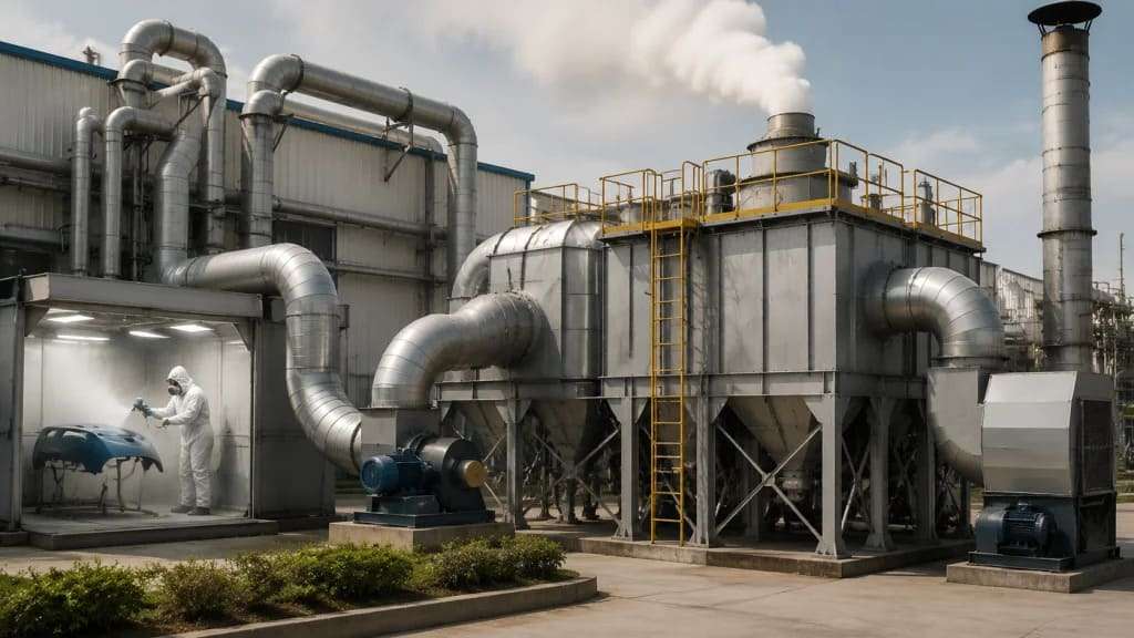
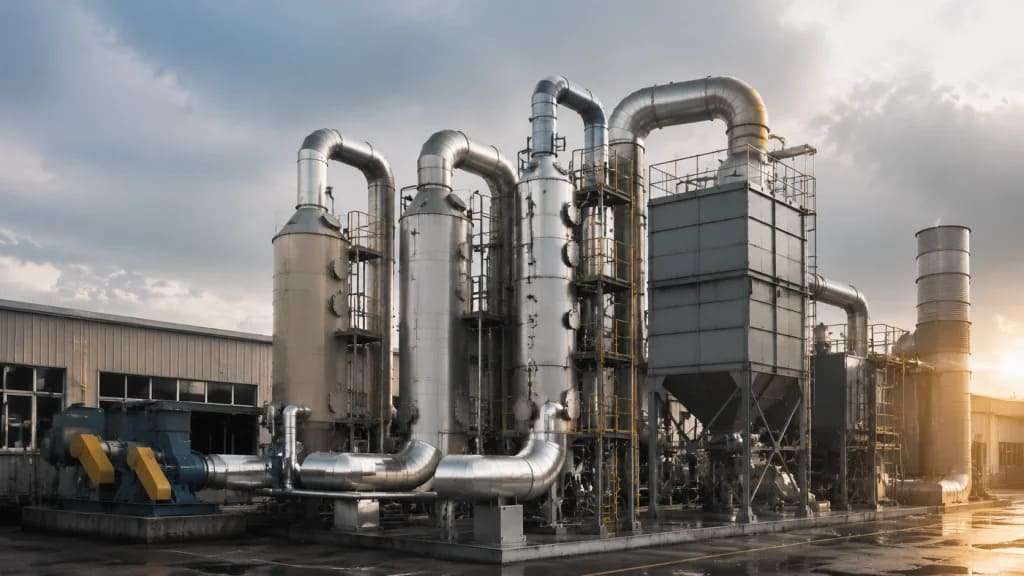
Industrial operations such as painting, printing, adhesive application, solvent cleaning, chemical synthesis, and petroleum refining generate exhaust streams containing Volatile Organic Compounds (VOCs)—carbon-based chemicals that evaporate readily at room temperature. A VOC treatment system (catalytic oxidizer, thermal oxidizer, or adsorber/concentrator) then converts these organic pollutants into carbon dioxide (CO₂) and water (H₂O) through oxidation, or captures them for recovery/recycling. This reaction or capture process destroys or removes up to 99%+ of VOCs. Finally, the cleaned exhaust is released to the atmosphere, meeting local emission regulations (e.g., EPA, EU Industrial Emissions Directive, China GB standards). This treatment process ensures that industrial facilities operate within legal limits while protecting worker health and reducing photochemical smog formation (ground-level ozone).
Unlike automotive exhaust, which has relatively consistent flow rates and temperatures, industrial VOC streams vary dramatically in:
– Concentration: From <10 ppm (dilute air in large paint booths) to >10,000 ppm (solvent recovery, chemical loading).
– Flow rate: From 100 m³/h (small laboratory hood) to >500,000 m³/h (large web printing or coating lines).
– Temperature: Ambient (20–30°C / 68–86°F) to hot (200–300°C / 392–572°F) from drying ovens.
– Humidity, particulate loading, and catalyst poisons (sulfur, chlorine, silicon).
No single technology fits all applications. The industrial VOC technical route is defined by matching the abatement method to the specific process conditions.
Primary VOC treatment technologies:
| Technology | Operating Temp | Destruction Efficiency | Best For |
| Catalytic Oxidizer (CO) | 300–450°C (572–842°F) | 95–99% | Medium concentration, stable flow, no poisons |
| Regenerative Thermal Oxidizer (RTO) | 800–900°C (1472–1652°F) | 95–99%+ | High flow, low concentration, variable conditions |
| Regenerative Catalytic Oxidizer (RCO) | 350–500°C (662–932°F) | 95–99% | Energy-efficient alternative to RTO with catalyst |
| Rotary Concentrator + Oxidizer | Ambient → 200°C | 90–99% | Very large flow, very low concentration |
| Carbon Adsorption (Recovery) | Ambient | 90–99% | Solvent recovery, high-value VOCs |
| Biofiltration | Ambient (15–35°C) | 60–90% | Very low concentration, large flow, no thermal energy |

The journey of VOC-laden air from the industrial source to the stack follows a precise thermal and chemical path. We describe the Catalytic Oxidizer (CO) as the reference technology, given its similarity to automotive catalysts, followed by key variations.
The process begins at the industrial source: a paint spray booth, a rotogravure printing press, a flexographic line, a chemical reactor vent, a tank farm breather valve, or a soil vapor extraction (SVE) system. A collection hood and ductwork capture the VOC-laden air, preventing fugitive emissions into the workplace. A fan (induced draft or forced draft) moves the air through the system.
Typical inlet conditions (example: web offset printing):
– Flow: 50,000 m³/h
– VOC concentration: 300–500 ppm as carbon (primarily aliphatic hydrocarbons, alcohols, esters)
– Temperature: 35°C (95°F)
– Humidity: 40–60% RH
Before the VOC-laden air enters the oxidizer, it must be cleaned of particulates and aerosols that would poison or blind the catalyst.
Filtration stages:
– Primary filter (G4 / MERV 8): Captures coarse dust >10 µm.
– Secondary filter (F7 / MERV 13): Removes fine particulates >1 µm (paint overspray, lint, metal fines).
– Optional HEPA (H13 / MERV 17+): For applications with submicron aerosols or strict permitting requirements.
Other pre-treatment (as needed):
– Quench / Cooler: Reduces temperature if the source exceeds catalyst limits (>500°C / 932°F) or to protect a rotary concentrator.
– Humidity control: Dehumidification if relative humidity exceeds 80–85% (water competes with VOC for adsorption sites on zeolite or carbon).
– Siloxane removal (landfill biogas): Activated carbon or specialized media to protect the catalyst.
Why pre-treatment is mandatory: Catalyst poisons (silicon from paint additives, chlorine from degreasers, sulfur from fuels, phosphorus from lubricants, lead from soldering) permanently deactivate the precious metal sites. Particulates physically mask the active surface. A well-designed filtration system extends catalyst life from months to 5+ years.
The filtered VOC-laden air enters a primary heat exchanger (plate, shell-and-tube, or run-around coil), where it is preheated by hot exhaust gases leaving the oxidizer. This recovers 50–70% of the thermal energy, dramatically reducing fuel consumption.
Heat exchanger types:
– Plate-type (gas-to-gas): Compact, 60–65% efficiency, used for clean streams.
– Shell-and-tube: Robust, handles some particulate, 50–60% efficiency.
– Run-around coil (liquid-coupled): Allows separation between dirty and clean sides, lower efficiency (40–50%).
After preheating, a burner (natural gas, propane, or electric) raises the air temperature to the **catalyst light-off temperature**—typically 300–400°C (572–752°F), depending on the VOC species and catalyst formulation.
Energy balance: For a well-designed system, the heat of combustion from the VOCs themselves (exothermic) may sustain the reaction after startup. At steady state, the burner modulates to maintain setpoint, often firing at 0–30% of maximum capacity.
The preheated VOC-laden air enters the catalyst bed—typically a flow-through ceramic or metallic monolith (honeycomb), or ceramic pellets packed in a bed.
Catalyst composition:
– Precious metals: Platinum (Pt) and palladium (Pd) on a high-surface-area washcoat (alumina, titania, or zeolite). Typically 0.5–3 g/L of PGM loading.
– Base metals (lower cost, higher temperature): Manganese dioxide (MnO₂), copper oxide (CuO), cobalt oxide (Co₃O₄). Used for high-temperature applications (>450°C / 842°F) or less demanding destruction requirements (90–95%).
– Zeolite (non-precious, for certain chlorinated VOCs): Hydrophobic zeolite (e.g., ZSM-5, Beta) adsorbs and oxidizes VOCs at higher temperatures (400–550°C / 752–1022°F).
Chemical reaction (complete oxidation):
For a generic VOC: **CₓHᵧ + (x + y/4)O₂ → xCO₂ + (y/2)H₂O + Heat**
Example (toluene, common in paints): C₇H₈ + 9O₂ → 7CO₂ + 4H₂O
Key parameters:
– Space velocity (SV): Volumetric flow rate of gas ÷ catalyst volume. Typical range: 10,000–30,000 hr⁻¹ (inverse: residence time 0.12–0.36 seconds).
– Conversion efficiency: 95–99% for properly designed systems. Regulatory requirements often specify 95% or 98% destruction removal efficiency (DRE).
– Temperature rise across catalyst (ΔT): Directly proportional to VOC concentration. Each 1,000 ppm (as methane equivalent) raises temperature by approximately 15–20°C (27–36°F).
Light-off curve: At low temperatures, conversion is negligible. As temperature increases, conversion rises sharply at the “light-off point” (typically 250–350°C / 482–662°F). Above 400°C (752°F), conversion plateaus at 95–99%. Excess temperature (>550°C / 1022°F) accelerates catalyst sintering (loss of surface area) and should be avoided via bypass or dilution.
The hot, cleaned exhaust (now with >95% of VOCs destroyed) passes through the secondary side of the heat exchanger (where it preheats incoming air) and is then discharged to the stack.
Stack monitoring (regulatory requirement for most permits):
– Continuous emissions monitoring system (CEMS) for large sources (>50,000 m³/h): Measures VOC (as total carbon), CO, NOx (from burner), and O₂.
– Periodic stack testing (annual or semi-annual): Reference method (EPA Method 25A or 25C, EN 12619) using flame ionization detection (FID) or gas chromatography.
– Alarm & bypass: If stack VOC exceeds permit limit (e.g., 20 ppm as carbon), the system must alert operators or automatically divert flow.
For very large flow rates (100,000–500,000+ m³/h) with low VOC concentrations (100–500 ppm), catalytic oxidizers become impractical due to large catalyst volumes and high preheat energy. The RTO solves this with **ceramic heat recovery media** (saddles or structured blocks) that achieve 95–97% thermal efficiency.
RTO operating cycle (typically 3, 5, or 7 chambers):
RTO vs. Catalytic Oxidizer (CO):
| Parameter | RTO | CO |
| Thermal efficiency | 95–97% | 50–70% |
| Operating temperature | 800–900°C | 300–450°C |
| Fuel consumption (at steady state) | Very low (autothermal if >300–400 ppm) | Moderate |
| Catalyst cost | None (ceramic media only) | High (PGM) |
| Footprint | Very large (multiple tall vessels) | Moderate |
| NOx formation | Higher (thermal NOx from burner) | Lower (lower temperature) |
| Maintenance | Valve wear, media cleaning | Catalyst replacement, pre-filter |
Best application: Web coating, large paint spray booths, flexible packaging printing, can manufacturing, chemical processing with variable VOC loads.
RCO combines the high thermal efficiency of RTO (95–97%) with the lower operating temperature of a catalyst (350–500°C / 662–932°F). Ceramic media beds provide heat recovery, and a catalyst layer (typically monolith or pellet) sits in or above the combustion chamber.
Advantages over RTO:
– Lower operating temperature saves fuel (30–50% reduction).
– Lower NOx formation.
– Smaller burner.
Advantages over CO:
– Much higher thermal efficiency (95%+ vs. 60–70%).
– Better tolerance for variable flow and concentration.
Disadvantage: Higher first cost than either RTO or CO (both media and catalyst), plus eventual catalyst replacement.
Best application: Medium-to-high flow (50,000–200,000 m³/h) with low-to-medium concentration (200–1,000 ppm), especially where natural gas is expensive or NOx permitting is stringent.
Some applications (cleanrooms, large paint booths with dilution air, semiconductor fabs) have massive airflows (200,000–1,000,000+ m³/h) but very low VOC concentrations (10–50 ppm). Oxidizing the entire stream directly is prohibitively expensive.
The concentration solution:
Overall energy consumption: 70–90% lower than direct oxidation of the full stream.
Best application: Large automotive paint booths (>500,000 m³/h), semiconductor manufacturing, cleanrooms, soil vapor extraction (SVE) with high airflows.
For high-value VOCs (e.g., toluene, xylene, acetone, ethyl acetate, alcohols in printing), destruction is wasteful. Carbon adsorption captures the VOCs and recovers the solvent for reuse.
Process:
Efficiency: 90–99% recovery typical.
Advantages: Solvent value offsets operating costs; no CO₂ from combustion; closed-loop carbon footprint.
Disadvantages: Cannot handle high boiling point VOCs (>120°C / 248°F); water-soluble VOCs contaminate condensate; steam generates wastewater; carbon must be replaced periodically (loss of activity due to polymerization or heavy ends).
Best application: Flexographic and rotogravure printing (toluene, ethyl acetate, isopropanol), adhesive coating (MEK, acetone), chemical cleaning (methylene chloride, though now regulated), tank farm vapor recovery.
For very low VOC concentrations (<100 ppm) and moderate temperatures (15–35°C / 59–95°F), biofiltration offers a low-energy, low-capital alternative to thermal oxidation.
Process:
– VOC-laden air is passed through a bed of organic media (wood chips, compost, tree bark, coconut fiber) or a synthetic structured packing.
– A biofilm of microorganisms (bacteria, fungi) grows on the media, feeding on the VOCs as a carbon and energy source.
– The microbes metabolize VOCs into CO₂, H₂O, and biomass (which must be periodically removed).
Advantages: Very low operating cost (fan energy only); no fuel or catalyst; low CO₂ footprint; proven for certain applications.
Disadvantages: Large footprint (long residence time 30–60 seconds); requires humidification (40–95% RH); limited to hydrophilic VOCs (alcohols, ketones, aldehydes, some aromatics); ineffective for chlorinated VOCs; seasonal temperature sensitivity; pressure drop increases as media compresses.
Best application: Wastewater treatment plant off-gases, soil vapor extraction with low concentrations, wood products manufacturing (formaldehyde, methanol), composting facilities.
Industrial VOC abatement systems are regulated by local, regional, and national authorities. Compliance requires:
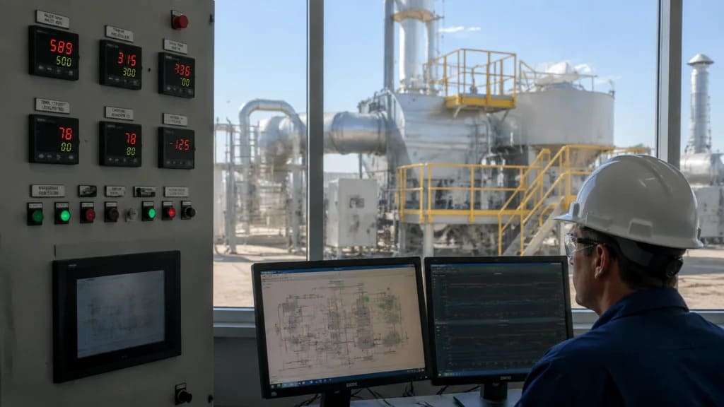
Continuous monitoring:
– Inlet VOC concentration (FID or PID sensor) – for system control and efficiency calculation.
– Stack VOC concentration (FID, GC-FID, or FTIR) – for permit compliance.
– Temperature (pre-catalyst, catalyst bed, stack).
– Pressure drop (across filters, catalyst bed, or RTO media) – indicates fouling or plugging.
– O₂ and CO (for combustion safety and completeness).
Periodic compliance tasks:
– Annual stack test by certified laboratory.
– Catalyst activity testing (pressure drop and conversion efficiency measurement).
– Filter replacement schedule (typically monthly to quarterly).
– RTO/RCO valve inspection and rebuild (every 1–3 years).
– Carbon change-out (every 1–5 years depending on application and regeneration).
Oxygen sensor & safety interlocks: For all thermal and catalytic oxidizers, a redundant oxygen sensor train and flame safeguard system ensures the burner does not fire without adequate combustion air—preventing explosion or incomplete combustion.
We don’t just manufacture catalytic oxidizers; we engineer them to meet the precise demands of your specific industrial VOC stream. Whether you require a low-temperature, high-space-velocity catalyst for a flexible packaging printing line with high ethanol and ethyl acetate loads, or a poison-resistant, high-PGM-loading catalyst for a silicone-coated release liner process with silicon-containing VOCs, our team can tailor the substrate geometry (monolith cell density or pellet size), washcoat chemistry (alumina, titania, or zeolite), and precious metal formulation (Pt-only, Pt/Pd, or base metal) to your exact exhaust composition, flow rate, and destruction efficiency target.
Partner with us to define your path to compliance.
With tightening global VOC regulations (China GB 37822-2019, EU Industrial Emissions Directive revision 2024, U.S. EPA Maximum Achievable Control Technology (MACT) standards), and the push for decarbonization, the industrial VOC route is evolving.
– Replaces natural gas burner with electric resistance heating or heat pump preheat.
– Benefit: Zero CO₂ from combustion; ideal for facilities with renewable electricity; smaller footprint (no gas train, no burner).
– Challenge: Higher operating cost where electricity is expensive; slower response to concentration spikes; limited to lower flow rates (electrical demand becomes prohibitive above ~50,000 m³/h).
– Some facilities (chemical, pharmaceutical) generate VOCs and NOx simultaneously. A dual-stage system: RTO (thermal oxidation of VOCs) followed by SCR (selective catalytic reduction of NOx from the burner).
– Benefit: Single system for both pollutants; meets stringent NOx limits (e.g., South Coast Air Quality Management District in California, <2.5 ppm NOx).
– Challenge: Complexity, cost, and higher pressure drop.
– Real-time sensors (inlet/outlet VOC, temperature, flow) feed a predictive model that:
– Estimates catalyst remaining useful life (based on thermal history and poison accumulation).
– Adjusts preheat temperature dynamically (minimizing fuel while maintaining compliance).
– Predicts filter change intervals and media replacement.
– Benefit: 10–20% energy savings; extended catalyst life; reduced unplanned downtime.
– Regulations now target per- and polyfluoroalkyl substances (PFAS)—”forever chemicals”—from industrial sources.
– Challenge: Traditional catalytic oxidation does not destroy PFAS; higher temperatures (1,000–1,100°C / 1832–2012°F) and longer residence times are required, plus post-treatment of HF acid gas.
– Solution: Advanced thermal oxidizers with acid gas scrubbers (wet or dry) are emerging for PFAS-laden air streams from semiconductor fabs, chrome plating, and textile finishing.
– Traditional VOC abatement systems are large, site-built facilities. New modular designs package CO, RTO, or concentrator systems in standard 20-ft or 40-ft shipping containers.
– Benefit: Reduced engineering and installation cost; faster deployment (weeks vs. months); scalable (add modules as production grows); mobile for temporary operations (remediation, construction).
– Application: Small printing shops, coaters, pharmaceutical R&D labs, biogas pretreatment, and emergency response.
The industrial VOC treatment system is not a commodity—it is a process-specific solution that balances capital cost, operating cost, destruction efficiency, compliance risk, and sustainability goals. A well-engineered system destroys 95–99%+ of VOCs, operates at the lowest possible temperature and fuel consumption, protects the catalyst or media for years of continuous service, and provides real-time data for both operators and regulators. Whether you operate a flexographic printing press, a chemical reactor, a paint booth, or a wastewater treatment plant, the right VOC abatement technology will define your environmental compliance, your operating budget, and your social license to operate—and we are ready to engineer the solution.