
Exploring the engineering behind the Gasoline Particulate Filter (GPF) and its role as the essential particulate filtration solution for modern stoichiometric gasoline engines, particularly Gasoline Direct Injection (GDI) systems.
Gasoline combustion in a direct injection engine generates exhaust containing not only gaseous pollutants (CO, HC, NOx) but also fine particulate matter (soot) due to incomplete fuel mixing and wall wetting. A Gasoline Particulate Filter (GPF) then traps these solid particles while allowing exhaust gases to pass through. Periodically, the trapped soot is passively oxidized (regenerated) during normal driving conditions. Finally, the cleaned exhaust—now with particulate number (PN) reduced by over 99%—exits the tailpipe alongside the Three-Way Catalyst’s (TWC) gas-phase conversion. This filtration-regeneration cycle ensures that modern GDI engines meet stringent PN limits (Euro 6d, China 6b, EPA Tier 3) without compromising the stoichiometric TWC pathway.
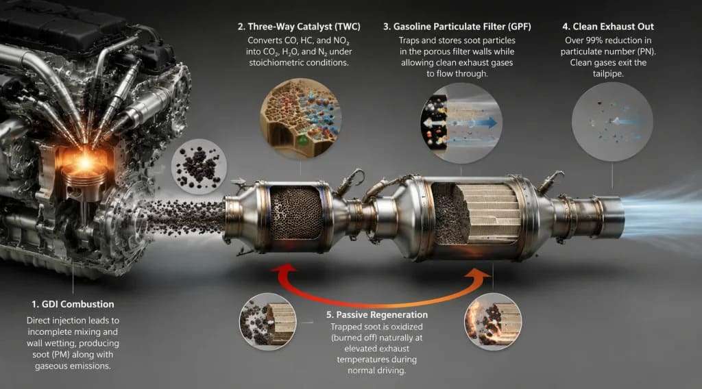
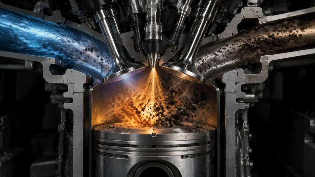
Unlike diesel engines, which have required particulate filters for nearly two decades, gasoline engines historically produced negligible particulate emissions due to port fuel injection (PFI), where fuel and air mix before entering the cylinder. However, **Gasoline Direct Injection (GDI)** —now standard on most new gasoline vehicles for its fuel economy and CO₂ benefits—injects fuel directly into the combustion chamber. This creates:
Fuel-rich zones where incomplete combustion generates soot.
Wall wetting on piston crowns and cylinder walls, leading to pool fires and particulate formation.
Higher pressures (up to 350 bar / 5075 psi) that atomize fuel but still produce nanoparticles (<23 nm).
Why the GPF is now mandatory:
– GDI engines produce 10–100x more particulates than PFI engines.
– Modern GDI vehicles without a GPF fail Euro 6d PN limits (6×10¹¹ particles/km) by a factor of 2–5×.
– Even with advanced injection strategies (multiple injections, high-pressure pumps), solid particles remain—especially during cold starts, high-load operation, and transient acceleration.
– Particulate toxicity is linked to particle number (ultrafine nanoparticles penetrate deep into lungs), not just particle mass—making GPFs essential for public health.

The journey of particulate-laden exhaust from a GDI engine through the aftertreatment system follows a precise path, with the GPF integrated alongside or combined with the TWC.
The process begins in the combustion chamber. Under stoichiometric operation, the Three-Way Catalyst efficiently handles CO, HC, and NOx. However, soot forms locally in fuel-rich pockets and near cold cylinder walls—areas where the air-fuel ratio is far from stoichiometric, even though the overall mixture is balanced. The Engine Control Unit (ECU) manages injection timing (typically 1–3 injection events per cycle), rail pressure (150–350 bar / 2175–5075 psi), and spark timing to minimize soot formation at the source. However, some soot is inevitable, especially during:
Cold starts (poor atomization, rich mixture).
High-load, high-RPM operation (limited mixing time).
Transient tip-in (sudden accelerator application).
The GPF handles whatever soot remains.
As exhaust exits the engine manifold and passes through the close-coupled TWC (where CO, HC, and NOx are converted), it then enters the GPF. The GPF shares the same wall-flow architecture as a DPF but is optimized for gasoline exhaust conditions.
Location: Typically downstream of the underfloor TWC, or increasingly **coated directly onto the GPF substrate** as a Four-Way Catalyst (FWC) or catalysed GPF (cGPF).
Filter substrate materials:
Cordierite: Low cost, good thermal shock resistance, lower filtration efficiency (typically 70–90%).
Silicon Carbide (SiC): Higher filtration efficiency (>95%), better thermal conductivity, higher cost.
Aluminum Titanate (AT): Emerging option, balancing cost and performance.
Filter structure:
Inlet channels:Open at the front, plugged at the rear.
Outlet channels: Plugged at the front, open at the rear.
Porous walls: Typically 10–15 µm thick with 15–25 µm pore size (larger than DPF pores to balance backpressure and filtration).
Filtration mechanism: Exhaust enters the inlet channels, passes through the porous walls (soot particles are trapped via diffusion, interception, and inertial impaction), and exits via the outlet channels.
Filtration efficiency:
Fresh GPF: 50–70% (particles larger than 50 nm captured).
Aged/soot-loaded GPF (active filtration): >99% for all particles down to 10 nm (soot cake layer acts as a high-efficiency filter).
Why efficiency increases with soot loading:The accumulated soot cake itself becomes a filter, trapping smaller nanoparticles that would otherwise pass through the fresh porous walls. This is the same phenomenon that makes DPFs more effective over time.
The most advanced GPF designs are not simple filters—they are catalysed GPFs (cGPF) or Four-Way Catalysts (FWC) , where the same TWC washcoat (platinum, palladium, rhodium on a high-surface-area support) is applied to the GPF substrate.
Location: Directly replaces the underfloor TWC, saving space and reducing backpressure by eliminating a separate catalyst brick.
Dual function:
Benefits of cGPF vs. separate TWC + GPF:
Space savings: One brick instead of two.
Lower backpressure: Fewer interface gaps and expansions/contractions.
Faster light-off: The filter substrate retains heat, improving cold-start conversion.
Cost reduction: One canning process, fewer sensors, less packaging complexity.
Challenge: The TWC washcoat reduces pore size slightly, increasing initial backpressurerequiring careful optimization of substrate porosity and washcoat loading.
Unlike diesel DPFs, which often require active regeneration (post-injected fuel burned on a DOC to raise temperature), gasoline GPFs regenerate passively during normal driving due to the inherently hotter exhaust of stoichiometric gasoline engines.
Regeneration chemistry:
With O₂ (dominant): C + O₂ → CO₂ (active above 500–550°C / 932–1022°F).
With NO₂ (minor role in gasoline): C + 2NO₂ → CO₂ + 2NO (NO₂ from TWC reactions).
Gasoline exhaust temperatures:
Cruising: 400–600°C (752–1112°F) — sufficient for moderate soot oxidation.
High load / full throttle: 700–850°C (1292–1562°F) — rapid, complete regeneration.
Cold start / idle: 150–300°C (302–572°F) — soot accumulates, but this is acceptable for short periods.
Result: Under most driving cycles (WLTP, FTP-75, RDE), the GPF reaches temperatures high enough to burn off accumulated soot continuously or during brief high-load events. No active regeneration strategy (post-injections, exotherms) is required—a major advantage over diesel DPFs.
Edge cases requiring active strategies:
– Mild hybrids (engine runs less frequently, lower average temperatures).
– Plug-in hybrids (extended electric driving followed by cold engine start).
– Low-load city driving (never reaching 550°C / 1022°F).
In these cases, the ECU may employ:
Spark retard: Delays ignition timing, sending more heat to the exhaust (at a fuel economy penalty).
Increased idle speed (for hybrid charge-maintenance modes).
Late post-injection (rare in gasoline, but possible with certain injector designs).
GPF health is monitored by several sensors and models:
Differential Pressure Sensor: Measures pressure drop across the GPF (P1 upstream – P2 downstream). The ECU calculates soot load using delta-P, exhaust mass flow, and temperature—then triggers any needed regeneration actions (though rarely required for gasoline).
Temperature sensors: Upstream and downstream of GPF to ensure regeneration does not exceed substrate limits (typical max: 850°C / 1562°F for cordierite, 900°C / 1652°F for SiC).
Soot load model: The ECU estimates soot accumulation based on engine operating conditions (load, RPM, injection parameters, coolant temperature). When modeled load exceeds a calibrated threshold (e.g., 2–3 g/L), and exhaust temperature is low, the system may raise temperatures via spark retard.
OBD thresholds (Euro 6d/China 6b):
– GPF removal or failure triggers a MIL (malfunction indicator light).
– Excessive backpressure (clogged, ash-loaded filter) triggers a fault.
– Unlike diesel, there is generally no “limp home” for GPF regeneration failure—gasoline engines rarely reach critical clogging due to passive regeneration.
Ash accumulation (service-life limiter):
– Metallic ash from engine oil (calcium, zinc, magnesium, phosphorus) cannot be burned off.
– Ash accumulates over 150,000–200,000 km (93,000–124,000 miles) for most GPFs.
– End-of-life: Backpressure rises, fuel economy degrades, and replacement may be required for high-mileage vehicles.
We don’t just manufacture GPFs; we engineer them to meet the precise demands of your specific gasoline direct injection platform. Whether you require a high-porosity catalysed GPF (cGPF) for a 48V mild hybrid with low average exhaust temperatures, or a low-backpressure, high-filtration-efficiency SiC GPF for a high-performance turbocharged GDI engine, our team can tailor the substrate material, pore size distribution, wall thickness, channel density, and TWC washcoat chemistry to your exact particulate and gaseous emissions targets.
Partner with us to define your path to compliance.
With Euro 7 (expected PN limits of 6×10¹¹ particles/km for all driving conditions, including cold start and short trips) and increasingly stringent real-driving emissions (RDE) requirements, the GPF is no longer optional—it is mandatory for every GDI vehicle sold in regulated markets.
The modern high-efficiency gasoline route now looks like this:
Engine → Close-Coupled TWC → Catalysed GPF (cGPF) / Four-Way Catalyst → Tailpipe
TWC washcoat applied directly to a GPF substrate mounted in the close-coupled position (directly to the exhaust manifold).
Benefit: Rapid light-off for both gas conversion and particulate filtration—critical for cold-start PN compliance (the majority of particulate emissions occur in the first 60 seconds of operation).
Challenge: Higher thermal stress (exhaust manifold temperatures >950°C / 1742°F) requires advanced substrate materials (SiC or specialized cordierite) and robust washcoat formulations.
Resistive heating elements embedded in or before the GPF.
Benefit: Enables PN control during cold starts and extended low-load operation (hybrid vehicles, urban delivery). The GPF reaches light-off temperature (for soot combustion) in seconds, eliminating the cold-start particulate spike.
Application: Plug-in hybrids, range-extender EVs, and next-generation Euro 7 vehicles targeting near-zero PN emissions under all conditions.
– Small, high-cell-density TWC close-coupled (for fast light-off of gases), followed by a larger, high-porosity cGPF underfloor (for particulate filtration and polishing gas conversion).
Benefit: Optimizes each brick for its specific function—gas conversion for the close-coupled TWC, filtration for the underfloor GPF.
Application: High-performance vehicles and large SUVs with high exhaust flow rates.
– Emerging low-temperature combustion concepts (GCI, HCCI, PCCI) produce very low NOx and particulates but require aftertreatment.
Role of GPF: Still required for PN compliance, but regeneration becomes more challenging due to lower exhaust temperatures (similar to diesel).
– Solution: Active regeneration strategies (spark retard, post-injection) or electrically heated GPFs.
– Synthetic fuels (e-fuels): Near-zero sulfur and aromatics, drastically reducing soot formation. GPF regeneration intervals extend, and filtration efficiency requirements may relax—but GPFs remain necessary for nanoparticle control.
– Higher ethanol blends (E20, E85): Oxygenated fuel reduces soot formation but increases aldehyde emissions (not a particulate issue). GPF still beneficial for PN compliance.
– Hydrogen combustion (H₂-ICE for gasoline-derived engines): No carbon, hence zero soot—GPF is not required. However, NOx remains, requiring SCR.
The GPF is not merely a diesel DPF adapted for gasoline—it is a fundamentally different device optimized for higher temperatures, passive regeneration, and integration with TWC chemistry. A well-engineered GPF balances >99% filtration efficiency, <5 kPa backpressure at rated power, and 150,000+ km durability while adding no active regeneration burden to the engine control strategy. Whether you are developing a small-displacement turbo GDI, a high-performance V8, or a plug-in hybrid, the GPF will define your particulate compliance—and we are ready to engineer the solution.