
Exploring the engineering behind turbocharger lubrication lines—the critical fluid conduits that deliver clean oil to the turbocharger bearing system and return waste oil to the engine sump under extreme thermal and flow conditions.
A turbocharger operates at speeds exceeding 100,000 RPM and temperatures that can reach 800–1,000°C (1,472–1,832°F) at the turbine housing. The bearing system requires a continuous supply of clean, pressurized oil to maintain the hydrodynamic fluid film that supports the shaft. Turbo oil feed and return lines are the arteries and veins of this lubrication system. The feed line delivers pressurized oil (typically 40–60 psi / 2.8–4.1 bar) from the engine’s main oil gallery to the turbocharger bearing housing. The return line (drain line) carries waste oil back to the engine crankcase or oil pan by gravity or scavenge assist. A well-engineered oil line system ensures adequate flow, prevents oil coking (carbon deposits from superheated oil), resists thermal fatigue, and maintains a leak-free seal across thousands of thermal cycles.
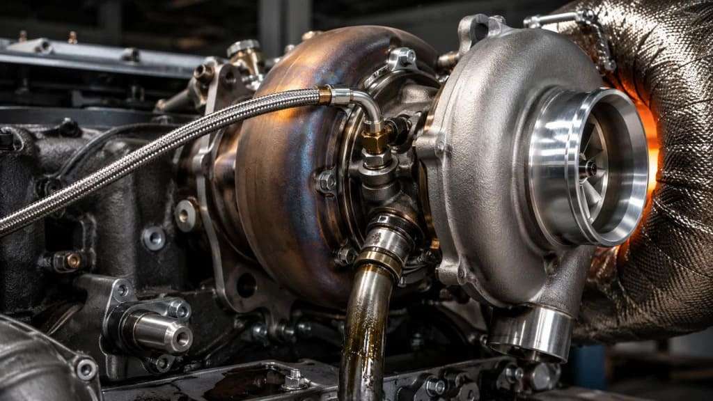
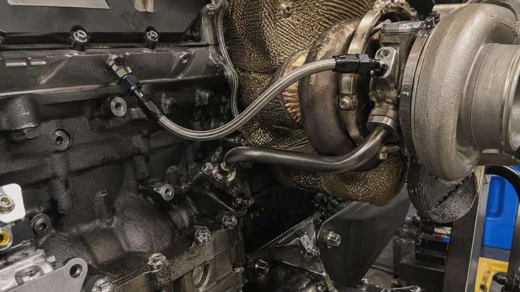
Oil lines must survive extreme temperature gradients, high vibration, and corrosive exposure while maintaining consistent flow.

The journey of exhaust gas from the engine cylinder to the tailpipe follows a precise technical path designed to maximize catalyst efficiency.
Function: Supply clean, cool engine oil to the turbocharger bearing housing under pressure. The oil enters through the center housing, passes through precision-drilled passages, and forms a hydrodynamic film between the shaft and bearings.
Construction materials:
Critical design requirements:
Parameter | Specification | Consequence of Deviation |
Internal diameter | 4–8 mm | Too small = oil starvation; too large = pressure drop, excessive flow |
Pressure rating | 100+ psi (7+ bar) | Below rating = rupture, oil loss, turbo seizure |
Temperature rating | -40°C to +200°C continuous | Below rating = embrittlement, cracking |
Bend radius | Minimum 3× tube OD | Tighter = kinking, flow restriction |
Flow considerations: The feed line incorporates a restrictor (orifice) on many applications to meter oil flow. Turbochargers require specific oil flow rates—typically 1–3 liters per minute at operating temperature. Too much oil can overwhelm the return system, causing seal leakage; too little oil causes bearing failure .
Banjo bolt assemblies (common in compact installations):
Function: Return waste oil from the turbocharger bearing housing to the engine crankcase. Unlike the pressurized feed, the return line operates by gravity—the turbocharger must be mounted higher than the oil entry point on the engine, with a continuous downward slope.
Construction: Larger diameter than feed line (typically 12–19 mm ID) to prevent backpressure. Low-pressure hose or pipe—silicone or reinforced rubber with spring-loaded clamps, or steel tubing.
Critical slope requirement: The return line must have a continuous downward slope of at least 10–15° (minimum 1 inch drop per 6 inches of horizontal run). Any dips, kinks, or horizontal sections allow oil to pool, causing backup into the turbocharger bearing housing. Oil backup forces oil past the turbine shaft seals, resulting in oil burning (blue smoke from exhaust), seal damage, and turbo failure .
Venting: The return line must be vented to the crankcase (open system) or include a vent line to prevent air lock. Aerated (foamy) oil returning from the turbo must be de-aerated in the sump before recirculation—foamed oil cannot maintain hydrodynamic bearings .
Heat management: Oil lines routed too close to exhaust manifolds or turbine housing experience oil coking—carbon deposits form when oil temperature exceeds 250°C (482°F), blocking the line. Solutions include:
Kink prevention: Sharp bends or crushed tubes restrict flow. Feed line kinking causes oil starvation—bearing seizure. Return line kinking causes oil backup—seal failure, blue smoke. Replace damaged lines—do not attempt to straighten or repair kinked tubes .
Abrasion protection: Engine vibration causes oil lines to contact adjacent components (engine block, chassis, wiring harnesses). Chafing leads to pinhole leaks. Install rubber grommets, P-clips with rubber inserts, or spiral wrap at contact points.
Vertical mounting allowance: Ideally, the turbocharger oil outlet is positioned at the lowest point of the bearing housing. On many installations, the turbo sits high relative to the crankcase (good) but may require custom-fabricated lines to achieve the necessary downward slope .
Failure Mode | Symptoms | Root Cause | Prevention |
Oil starvation | Turbo noise (whine or grinding), loss of power, bearing seizure | Restricted feed line (coked oil, debris, kink) | Replace feed line at turbo replacement; use quality oil; follow change intervals |
Oil coking (feed line) | Gradual power loss, eventual turbo failure | Heat soak after shutdown—oil stagnates in hot bearing housing | Turbo timer (idle before shutdown); post-shutdown cooling fan; synthetic oil |
Oil backup (return line) | Blue exhaust smoke, oil in charge air cooler, seal leakage | Kinked or blocked return line; turbo mounted too low; line slope insufficient | Verify continuous downward slope; clear blockages; replace damaged lines |
External leakage | Oil spots under vehicle, burning oil smell on hot components | Cracked line (thermal fatigue); loose banjo bolt; failed crush washer | Torque to specification; inspect lines for cracks at oil change intervals |
Contamination-induced failure | Premature bearing wear or seizure | Debris (RTV silicone, metal shavings, carbon chunks) in feed line | Never use sealant on oil line fittings—use only gaskets or crush washers |
Diagnostic flow (service procedure):
Integrated oil passages (pedestal mounting): Modern engines increasingly eliminate external oil lines entirely. A utility pedestal cast into the engine block or cylinder head contains internal oil supply and drainback passages. The turbocharger mounts directly to the pedestal—oil flows through drilled passages without external hoses or pipes. Advantages: no leak paths, no abrasion risk, compact packaging. The return passage is isolated from moving engine parts—prevents foamed oil from contacting rotating components before de-aeration .
Scavenge pump systems (low-mount turbochargers): Some applications (rear-mounted turbos, hybrid vehicles) cannot achieve gravity drain—the turbo sits lower than the oil level in the crankcase. A scavenge pump (electric or engine-driven) actively pulls oil from the turbo and returns it to the sump. Systems use a hydraulic motor/pump assembly powered by pressurized engine oil—no additional electrical or mechanical drive required .
Gas turbine applications: Turbofan and turboshaft engines use complex scavenge pipe assemblies with internal bends and perforations to separate air from oil before returning to the tank. Bends induce flow stratification—air separates from oil, preventing foaming and tank vent blockage .
We don’t just supply oil lines—we engineer complete lubrication delivery systems for turbocharged applications. Whether you require a direct-fit OE replacement feed line with integrated restrictor and banjo fittings, a high-temperature braided stainless line for a performance build, or a pedestal-mounted integrated oil passage design for a new engine platform, our team tailors tube diameter, material selection (steel, stainless, PTFE), heat shielding, and routing geometry to your turbocharger’s specific flow requirements, underhood packaging constraints, and thermal environment.
Partner with us to define your path to compliance – lubricated for life.
Integrated oil cooling passages: Oil lines that incorporate cooling fins or coaxial water jackets—reduces oil temperature before it enters the turbo bearing housing. Extends oil life, reduces coking.
Smart oil lines with embedded sensors: Thermocouples or flow sensors integrated into the oil line fitting—provides real-time oil temperature and flow data to ECU. Enables predictive maintenance (detect coking before failure) and active cooling control.
Carbon-composite oil lines: Ultralight, high-temperature resistant, fatigue-proof. Currently cost-prohibitive for production but used in motorsports. Potential for future high-performance applications.
Self-cleaning anti-coking coatings: Internal surface treatments (PTFE, DLC – diamond-like carbon, or ceramic) prevent carbon adhesion. Oil coking deposits cannot bond to the coating—reduced feed line blockage risk.
The turbo oil feed and return line is not a simple pipe—it is a precision fluid conduit operating at the edge of material limits. A well-engineered oil line system delivers consistent, contaminant-free flow across temperature swings from -40°C winter starts to 200°C+ sustained operation. Whether you are replacing a failed turbo on a Chevrolet Cruze, building a performance engine with a low-mount turbo requiring a scavenge pump, or designing a new production engine with pedestal-mounted integrated passages, the oil feed and return lines will define your turbocharger’s reliability and service life—and we are ready to engineer the solution .